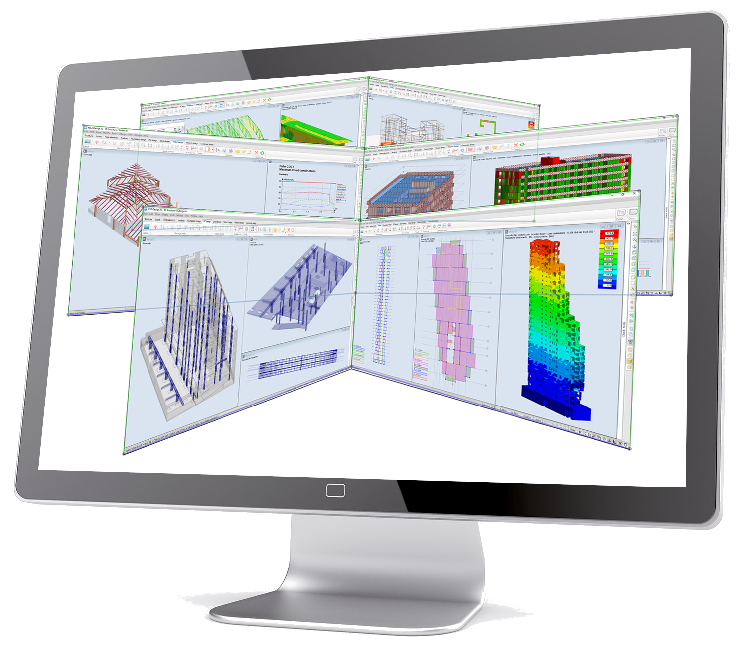



Features of FEM-Design
Advanced 3D Modelling
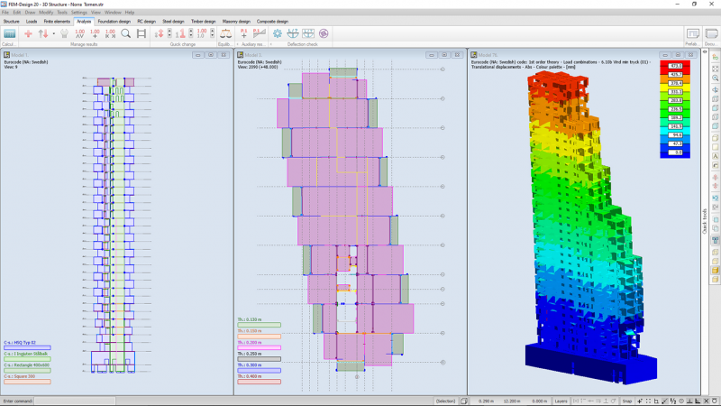
FEM-Design’s specialty is advanced 3D modelling and design of finite elements for load-bearing concrete, steel, timber, and foundation structures. Everything is done according to Eurocode with NA. It also has an intuitive working environment that is based on popular CAD tools for structure editing and model creation. Consequently, FEM-Design is a natural choice for various tasks in the construction industry due to its wide range of modelling options. That makes it a structural engineer’s best friend.
Cross Laminated Timber
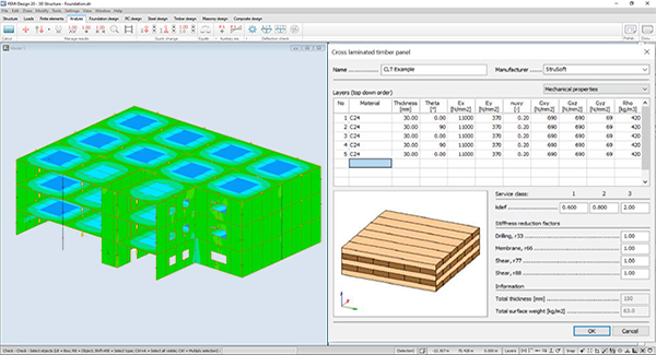
- Based on Laminated Shell Theory
- Point based stress detailed results
- Shell based stress detailed results
- Design checks according to Eurocode 5
- Torsional check & shell buckling

Precast concrete
- Elastic and plastic connections
- Detach connection per direction & component
- Connection forces and resultants
- Overturning of walls
- Sliding of edge connections

Geotechnics - 3D Soil
- Nonlinear 3D soil model: Mohr-Coulomb plasticity
- Soil-structure interaction and their nonlinear effects
- Bedding modulus automatic calculation
- Cantilever retaining walls
- Slope stability
Parametric design
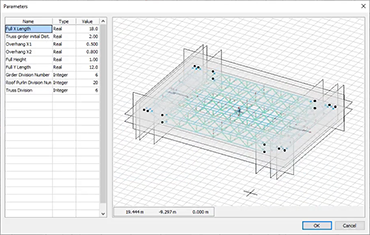
FEM-Design contains a parametric model option that allows you to streamline workflows. With this tool you can easily enter and modify standard structures. Moreover, you can build parametric structural frame-, shell- or complex-systems.
IFC, Revit and API support
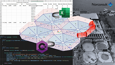
With FEM-Design it will be easy to read IFC models. Native and editable analytical model elements can be created equally as easily. Through the StruSoft StruXML Revit Add-In, FEM-Design has a direct communication link with Autodesk Revit Structure. As such, the transfer of the analytical model and its properties between FEM-Design and Revit is done in a fast manner. Another one of FEM-Design’s features is an API used for task automation and parametric design. This application programming interface (API) works on extensible markup language (XML), which allows the user to fully control the software. Moreover, FEM-Design makes use of toolboxes, such as Dynamo and Grasshopper.
Masonry Design
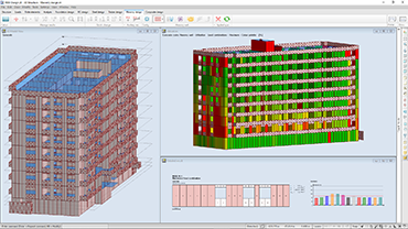
The Masonry Design module in FEM-Design offers definition of brick material but only for plane wall objects. To calculate the effect of the mortar on design, the user can look at the masonry brick + mortar combination or specifically at the masonry unit brick. Afterward, using Wall Strips, the user can calculate the masonry design, with input of a wall strip width. The results provided by the Masonry Design module are the utilization rate and the internal and detail forces per strip.
Composite column design
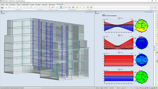
Check composite columns with FEM-Design, according to Eurocode 4 (EN 1994-1-1 6.7.3). This is called the “Simplified method”, whereby relying on the theoretical interaction surface you can design reinforcement and cross-sections.
Construction stages
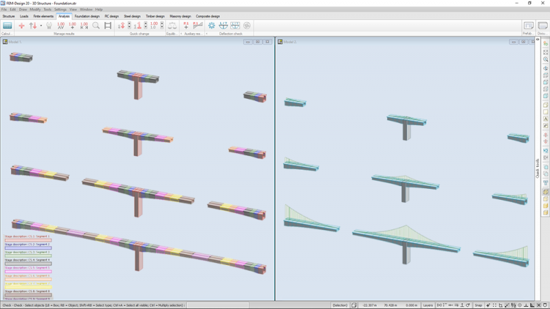
In FEM-Design you can create as many construction stages as your project requires. Then, you can assign them the structural elements you need. The construction stages can either be generated automatically or set manually by storeys. Similarly, initial stress state property can be set for each of the stages.
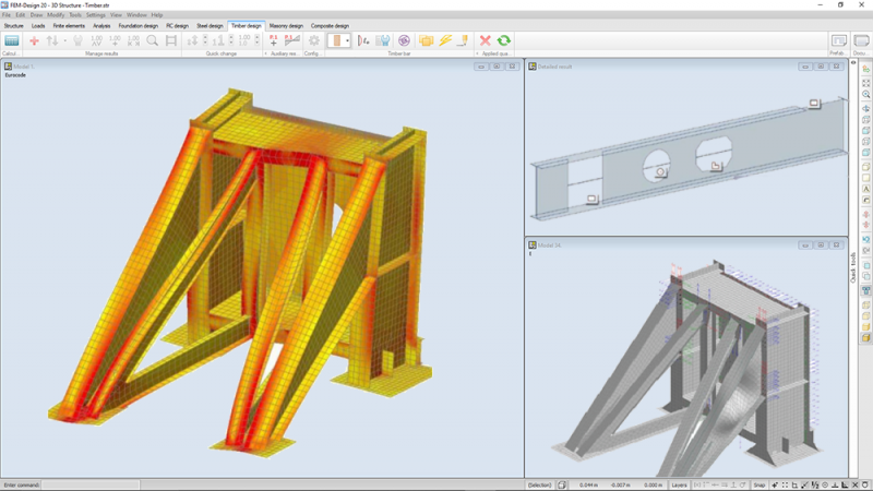
Steel shell design
Do you want to model a steel bar as a real 3D element made of steel plates? You can do that with one click in FEM-Design. Use the steel shell model to insert holes, add plates, stiffener elements, buckling support or even cut parts out.
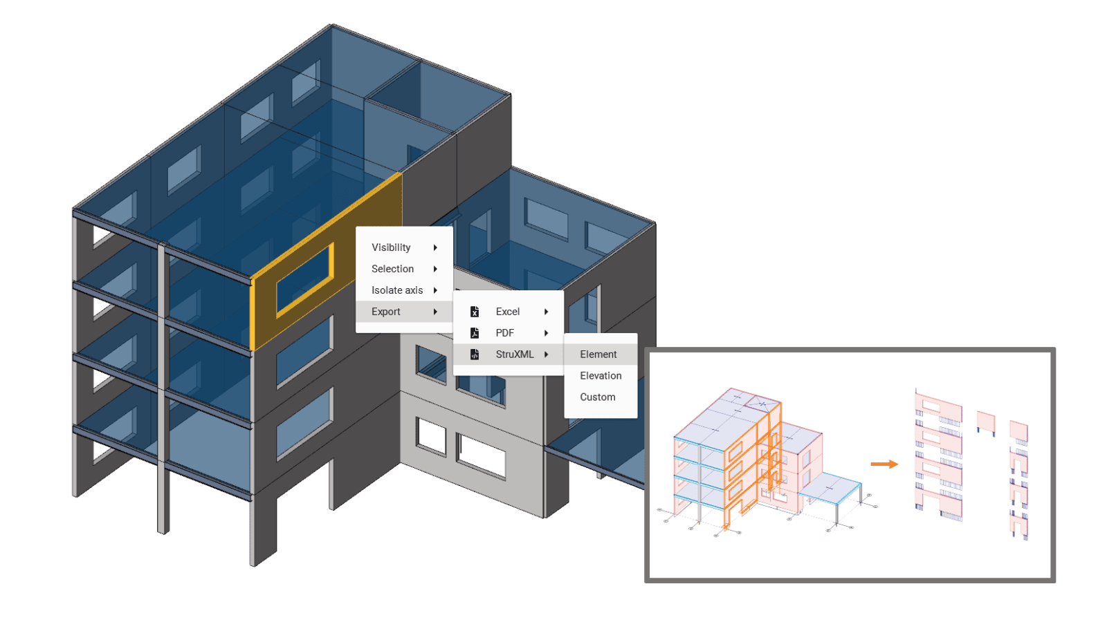
PREFAB
PREFAB is an extension to FEM-Design that reads your analysis results and compiles them into standardized, component level load documentation for precast concrete and CLT projects. PREFAB supports 3 data treatment approaches: direct FEM-Design results (1), simplified results for cleaner component handover (2) or plastic redistribution for lower bound optimization (3). Outputs include interactive PDFs with toggleable layers and tooltips, FEM-Design exports for wall, plate, and foundation design, or locked files for PREFAB Viewer. No parallel modelling, no manual reentry. Click to learn more about PREFAB on StruSoft.com.
FEM-Design Videos
Watch the software and webinar videos on GoTo stage: